PIKA - User Guide
LoRaWAN Converter
Installation Requirements for the Product Substrate and Powering Up

1. Product Introduction
Welcome to the user manual for PIKA. This document will provide you with all the information you need to get started with and use the software effectively.
1.1 Overview
PIKA: A Smart and User-Friendly Bridge from Modbus RS485 to LoRaWAN.
PIKA is a device that enables industrial data collection and transmission using the LoRaWAN protocol. It supports both RS485 and pulse inputs and can communicate with up to 8 devices on the same bus. PIKA can read up to 50 Modbus registers and send them to the Internet via LoRaWAN. PIKA also allows users to remotely control and monitor data from various RS485 devices in real time. PIKA has a simple plug-and-play design that makes it easy to install and use.
1.2 Functional Specifications
-
LoRaWAN Communications: PIKA can connect to a LoRaWAN network and send data to the Internet via LoRaWAN gateways.
-
Modbus RTU Master: PIKA can act as a Modbus RTU master and read data from up to 8 Modbus RTU slave devices on the same bus. It can read up to 50 Modbus registers from each device and convert them to LoRaWAN payloads.
-
Digital Pulse Signals Counter: PIKA can also count digital pulse signals from devices such as water meters, gas meters, or electricity meters. It can send the pulse counts to the Internet via LoRaWAN.
-
Reporting at Set Intervals and Power Failure Alarm: PIKA can report the data from Modbus RTU and pulse counter inputs at regular intervals that you can configure. It can also send an alarm message to the Internet when it detects a power failure.
-
Instantly Send the Report with the Trigger Button: PIKA has a trigger button that you can press to instantly send the current data to the Internet via LoRaWAN. This is useful for testing or troubleshooting purposes.
-
Device Configuration through the WNESS Tool Software: PIKA can be configured using the WNESS Tool software that runs on your PC. You can use the software to set up the LoRaWAN, Modbus RTU, pulse counter, device ID, and password parameters for your device.
-
Software Configuration: LoRaWAN, Modbus RTU, Pulse Counter, Device ID & Password.
2. Hardware Introduction
2.1 Packing list
No. | Description | Picture |
|---|---|---|
1 | 1 x Type-C Cable & Power Adapter | |
2 | 1 x Terminal Block | |
3 | 2 x Wall Mounting Kits | |
4 | 1 x Quick Guide | |
5 | 1 x PIKA device | |
6 | 1 x Antenna |
2.2 Hardware Overview

2.3 LED Patterns and User Button
The User button is on the left top of the device.
Working Mode | Description | LED Status |
|---|---|---|
Run Mode | In this mode, the device only performs communication with the configuration software. Press the button once to switch the device to Run Mode after 3 seconds. | The Yellow LED blinks every 3 seconds. |
IDLE Mode | After completing all tasks in Run Mode, the device will enter IDLE Mode and wait until the next cycle based on the setting interval. Press the button once to switch to Stop Mode. | The Red LED blinks every 3 seconds. |
Stop Mode
(For Device Configuration) | At the start of a working cycle, the device executes tasks such as querying MODBUS and sending LoRa data. The button is disabled in this mode. | The Green LED blinks. |
To reset the device: Press and hold the button for 10 seconds.
2.4 Dimensions (mm)
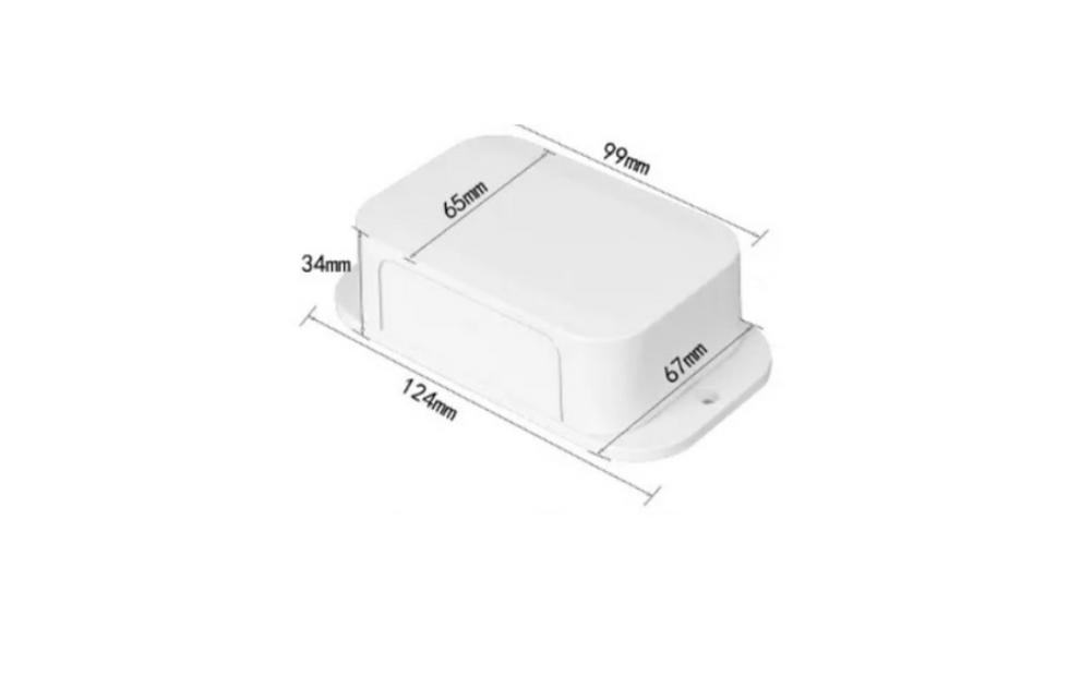
3. Operation guide
3.1 Log In to Software
For operation, first:
-
Power up the PIKA device, connect to the antenna and connect it to your computer via the USB type-C port.
-
Wait for about 1 minute for the device to start up. Once the Red light blinks every 3 seconds, the device has finished booting up.
-
Press the button once to put the device into the "Stop Mode” for configuration.
-
Then, open the "WNESS_Tool.exe" software, enter the default password (which is "123456"), select the Serial port connected to the PIKA device, and click "Connect".

5. Once you have logged into the software, the device parameters will be displayed in the "Status" tab.

3.2 LoRaWAN Settings
Tab “LoRaWan” is used for configuring the transmission parameters in the LoRaWAN network.
Click “Enable” to enable the feature to work.

No. | Parameters | Description |
|---|---|---|
1 | Regional Band | EU433, CN470, IN865, EU868, AU915, US915, KR920, RU864, and AS923-1/2/3/4. (Default AS923-2) |
2 | Class | A, B, C. (Default Class C) |
3 | Join Mode | OTAA and ABP modes are available. (Default ABP) |
4 | Device EUI | Set the device EUI, 16 digits. |
5 | App EUI | Set the device App EUI, 16 digits. |
6 | Application Key | Appkey for OTAA mode, 32 digits. |
7 | Device Address | DevAddr for ABP mode, 8 digits. |
8 | Network Session Key | Nwkskey for ABP mode, 32 digits. |
9 | Application
Session Key
| Appskey for ABP mode, 32 digits. |
10 | Application Port | The port is used for sending and receiving data. (Default 2) |
11 | Tx Power | The transmit power of device, 2dBm->16dBm (Default 16dBm)
|
12 | RX2 Frequency | RX2 frequency to receive downlinks. Unit: Hz (Default 921400000) |
13 | RX2 Data Rate | RX2 data rate to receive downlinks.
(Default 2) |
14 | ADR Mode | Allows the network server to adjust the data rate of the device. |
15 | Confirmed Mode | Configure the device to receive ACK packets from the network server.
|
16 | Send retry
| 0-3. (Default 0) |
Click the “Save” button to save the configuration.
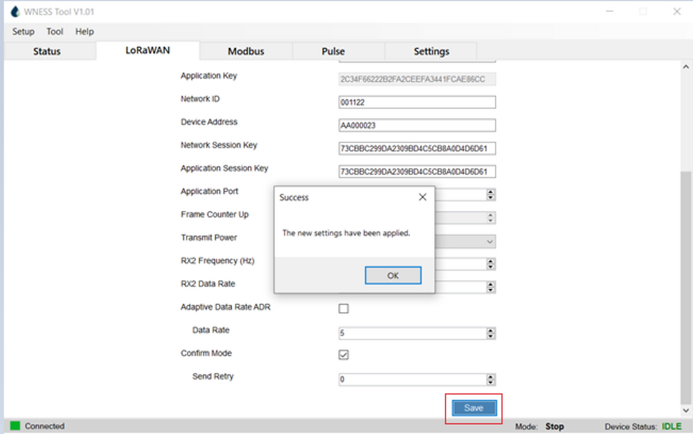
3.2.1 General Settings
3.2.1.1 Basic Settings

No. | Parameters | Description |
|---|---|---|
1 | Device ID | Show the SN of the device. |
2 | Reporting Interval | Transmit data to the network server every 1-1000 minutes. (Default: 15 mins.) |
3 | Change Password | Change the password to log in to the software.
(Default password: 123456.) |
Click the “Save” button to save the configuration.

3.2.1.2 RS485 Settings
PIKA has a single port, labeled as RS485, which is intended for connecting Modbus RTU devices.
-
To connect your device, you need to plug it into the RS485 port "A, B" in the terminal block.
-
Once connected, navigate to the Modbus > "Connection setup" section to enable and configure the serial port settings. Ensure that the serial port settings match those of your RS485 terminal device and then click "Enable" to activate the feature.
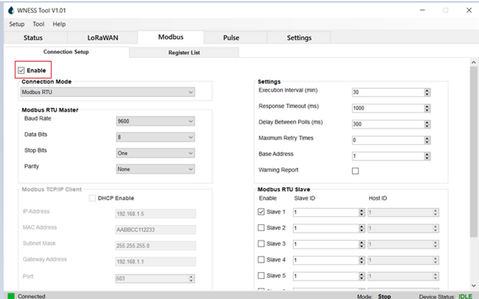
No. | Parameters | Description |
|---|---|---|
1 | Connection Mode | Modbus RTU or Modbus TCP/IP.
(Default Modbus RTU) |
2 | Baud Rate | 1200/2400/4800/9600/19200/38400/57600/115200 are available.
(Default 9600). |
3 | Data Bit | 8 bit/9 bit is available.
(Default 8). |
4 | Stop Bit | One bit / Two bits are available.
(Default One). |
5 | Parity | None, Odd and Oven are available.
(Default None). |
6 | Execution Interval
(min) | The execution interval between each Modbus channel command.
(Default 15 mins). |
7 | Response Timeout
(ms) | Response time for each data fetch.
(Default 1000 ms). |
8 | Delay Between Polls
(ms) | The maximum response time that the PIKA waits for the reply to the command. If it does not get a response after the max response time, it is determined that the command has timed out
(Default 300 ms). |
9 | Max Retry Time (ms) | Set the maximum retry times after the device fails to read data from the RS485
terminal devices.
(Default 0). |
10 | Base Address | 0 or 1 are available.
(Default 0). |
11 | Slave ID | 0->255. |
Click “Save” to save the configuration.
3.2.1.3 Modbus TCP Settings (Option)
-
Connect the TCP/IP device to the RJ45 port.
-
Then, go to Modbus and select "Connection Setup" to configure and enable serial port settings. Your serial port settings should match those of the Modbus TCP terminal devices.
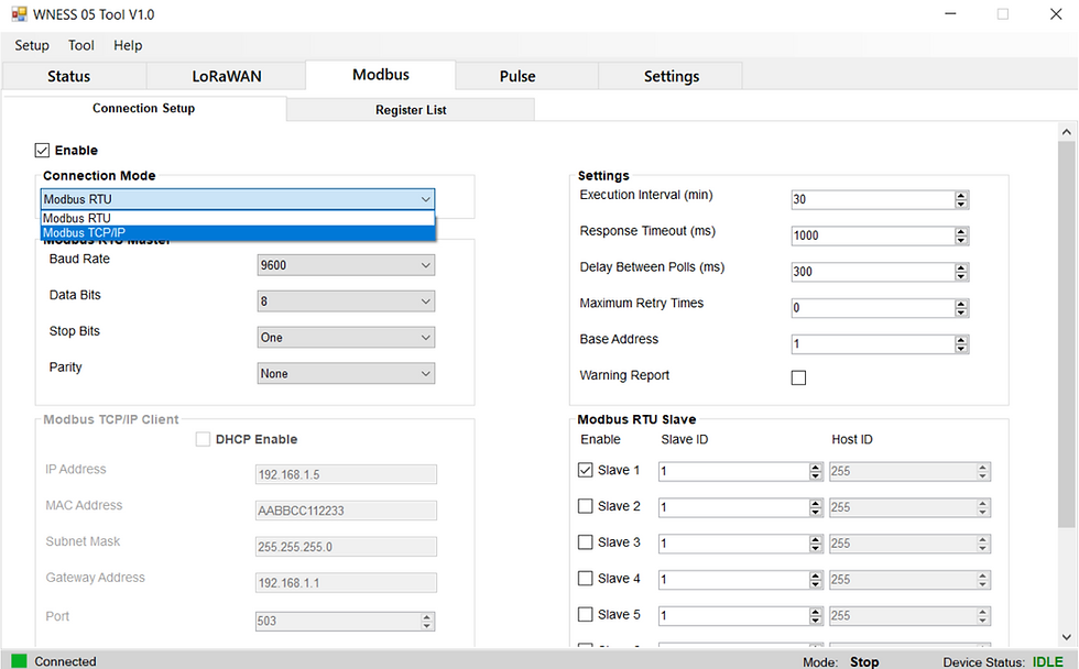
No. | Parameters | Description |
|---|---|---|
1 | Connection Mode | Modbus RTU or Modbus TCP/IP. |
2 | IP Address | Modbus device IP address. |
3 | MAC Address | |
4 | Subnet Mask | |
5 | Gateway Address | |
6 | Port | The default port is 502. |
7 | Connect Timeout (ms) | Device connection timeout. |
Go to “Register List” to enable RS485 and configure MODBUS registers:

No. | Parameters | Description |
|---|---|---|
1 | Poll Slave ID | ID to read data, same Slave ID. |
2 | Name | Customize the name to identify every MODBUS channel. |
3 | Address | The starting address for reading. |
4 | Register Type | Select the Register type of MODBUS channels. |
5 | Length | Set read how many digits from the starting address, 1->4. |
6 | Data Type | Select the data type of Modbus channels. |
7 | Byte Order | Set the MODBUS data reading order if you configure the type as Input register or holding register. |
8 | Warning | None, With, Without. |
9 | Warning Value | Input data to warning. |
10 | Cycle | Number of repetitions 1->5. |
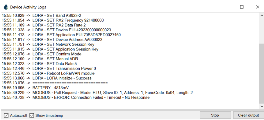
3. Click “Poll” to check if PIKA can read correct data from terminal devices. If there is no response, the device will return “Modbus Connection: Failed-Timeout- No Response”


4. The software comes with a feature to export and import Modbus register tables to/from .csv file format. Simply click on the option you need and follow the prompts to complete the process.

5. Click “Add” to add a new data line of register address.

6. Click the “Save” button to save the configuration.

Press the button once to activate Run Mode. The device will then read Modbus data and transmit it via LoRa.
3.2.1.4 Tool
To view the parameters from the return device, please follow these steps: Click on "Tool" and then select "Device Logs".

4. LoRaWAN Payload Format – Uplink Message
All LoRaWAN payload messages are encoded using TLV (Type-Length-Value) format. The TLV structure consists of three components: Type, Length, and Value.
-
Type: Specifies the type of data contained in the TLV structure and has a length of 4 bits.
-
Length: Indicates the length of the data in bytes and also has a length of 4 bits.
-
Value: Is the actual data being transmitted.
Due to the length limitation of the LoRaWAN payload, outgoing messages can be fragmented into multiple packets. These packets must be reassembled on the server side with the same Payload ID.
The format of the first LoRaWAN message packet sent is as follows:
Packet 1:
Define | Type (4bits) high | Length (4bits) low |
|---|---|---|
Device Model | 1 | 1 |
Status | 2 | 2 |
Warning | 3 | 1 |
Firmware Version | 4 | 1 |
Pulse Volume | 5 | 4 |
Reserved | 6 | |
Reserved | 7 | |
Reserved | 8 | |
Reserved | 9 | |
Reserved | 10 | |
Reserved | 11 | |
Reserved | 12 | |
Payload ID | 13 | 4 |
Modbus Slave ID | 14 | 1 |
Register 0 | 15 | |
Register 1 | 15 | |
Register ... | 15 | |
Register ... | 15 | |
Register ... | 15 |
Below is the format of the fragmented LoRaWAN message packets sent:
Packet 2 - Packet n:
Define | Type (4 bits) high | Length (4 bits) low |
|---|---|---|
Payload ID | 13 | 4 |
Modbus Slave ID | 14 | 1 |
Register 0 | 15 | |
Register 1 | 15 | |
Register ... | 15 | |
Register ... | 15 | |
Register ... | 15 |
4.1 Device Model Format
The device model with Type 1 (0x01) has length of 1 byte.
Device Model | Value |
|---|---|
PIKA-001 | 0x01 |
PIKA-002 | 0x02 |
... | ... |
4.2. Status Format
Status with Type 2 (0x02) has a length of 2 bytes, which includes the Battery Voltage for the battery-powered version. The voltage is stored in the 9 least significant bits.
Byte high | Byte high | Byte low |
|---|---|---|
Bit 7 - Bit 1 | Bit 0 | Bit 7 - Bit 0 |
Reserved | Battery voltage | Battery voltage |
4.3. Warning Format
A Type 3 Warning (0x03) is represented as a bit field with a length of 1 byte. If the bit value is 1, it indicates the presence of a warning, while 0 indicates no warning. The warnings that can be identified include MODBUS Connection Error, MODBUS Exception Error, MODBUS Parse Data Error, Low Battery Warning, and Power Outage Warning.
Warning | ||||||
|---|---|---|---|---|---|---|
Bit 7 - Bit 5 | Bit 4 | Bit 3 | Bit 2 | Bit 1 | Bit 0 | |
Set = 1
Reset = 0 | Reserved | Power Outage Warning | Low battery Warning | ErParse | ErException | ErConnection |
4.4. Firmware Version Format
Firmware Version with Type 4 (0x04) has length of 1 byte.
Firmware Version | Value |
|---|---|
V 01.5 | 0x0F |
V 12.8 | 0x80 |
... | ... |
4.5. Payload ID Format
Payload ID with Type 13 (0x0D) has length of 4 bytes.
4.6. Modbus Slave ID Format
Modbus Slave ID with Type 14 (0x0E) has length of 1 byte, containing the ID of the device being queried.
4.7. Modbus Register Value
The Modbus Register Value with Type 15 (0x0F) has a variable Length depending on the value of the register. The Length includes 2 bytes for the register address plus the length of the register value.
If the register value is 0, then the length is only 2 bytes, indicating that it only includes the length of the 2-byte register address, and there is no length for the register value.
Register 0,1,...,n
Define | Type | Length | Value | |
|---|---|---|---|---|
Register X | 15 | 2 bytes address + value length | 2 bytes register address | Register value: 0 - 8 bytes |
Example:
Define | Type Length Value - Raw (Hex) | Length (Dec) | Type (Dec) | Value (Hex) | Value (Dec) |
|---|---|---|---|---|---|
LoRa Payload Raw Data | 11012200003100D463 | D689D67ED67AF60001D6 | B06FB4E101FA0000D68D | 89D67EFA0002D67ED67A | D676D662FA0003D67AD676D662D65F |
Device Model | 0x1101 | 1 | 1 | 0x01 | WNESS05-001 |
Status | 0x220000 | 2 | 2 | 0x0000 | |
Warning | 0x3100 | 1 | 3 | 0x00 | No warning |
Payload ID | 0xD463B06FB4 | 4 | 13 | 0x63B06FB4 | 1672507316 |
Modbus Slave ID | 0xE101 | 1 | 14 | 0x01 | Slave ID: 01 |
Register 0 | 0xFA0000D68DD689D67ED67A | 10 | 15 | 0x0000D68DD689D67ED67A | Register Address: 0x0000, Register value: 0xD68DD689D67ED67A |
Register 1 | 0xF60001D689D67E | 6 | 15 | 0x0001D689D67E | Register Address: 0x0001, Register value: 0xD689D67E |
Register 2 | 0xFA0002D67ED67AD676D662 | 10 | 15 | 0x0002D67ED67AD676D662 | Register Address: 0x0002, Register Value: D67ED67AD676D662 |
Register 3 | 0xFA0003D67AD676D662D65F
| 10 | 15 | 0x0003D67AD676D662D65F | Register Address: 0x0003, Register Value: D67AD676D662D65F |
5. LoRaWAN Payload Format – Downlink Command
PIKA devices can be configured using downlink commands, which are encoded using TLV (Type-Length-Value), similar to uplink messages.
These commands are sent in hexadecimal format.
5.1. Report Interval Update
Below is an example of an update Report Interval:
Report Interval Update | |
|---|---|
Lora Raw data | 0x0102000A |
Type (1 byte) | 0x01 |
Length (1 byte) | 0x02 |
Value (2 bytes) | 0x000A = 10 minutes |
5.2. Send Uplink Now
Send this Downlink command to the device to have it transmit a Uplink message immediately afterward.
Send Uplink Now - Only available in Class C | |
|---|---|
Lora Raw data | 0x0302ABCD |
Type (1 byte) | 0x03 |
Length (1 byte) | 0x02 |
Value (2 bytes) | 0xABCD = Report Key |